Lately I have been working on setting up a Cisco CRS (16 Slot) Multi Chassis 2+1 system for one of my customers (a leading Service Provider in EMEAR). The activities lasted roughly a week, full of activities and challenges at the same time.
As you we already know the Cisco Carrier Routing System can be set-up to work in a Single mode (Single Chassis) or Multi system mode (Multi chassis). Benefits of running a Multi Chassis system is purely on Scalability and Capacity.
Let’s start with the basic components of a CRS Multi Chassis system:
- Line Card Chassis (LCC)
- Fabric Card Chassis (FCC)
- S13 Fabric Cards (Fabric Cards connecting the LCC to the FCC)
- S2 Fabric Cards (Fabric Cards on the FCC, special Cisco Cells traversing here)
- Optical Interface Modules (OIM – a Passive interconnection card of the Fiber Optical Cables between LCC and FCC, in other words between S13 and S2)
- Fabric Fiber Optical cables (Array cables)
- Shelf Controller Gigabit Ethernet card (SCGE)
The list above summarizes most of the components needed to build up a CRS Multi Chassis system.
LCC – is simply a Chassis where all the Line Cards (MSC, FP), PLIM’s, SFC, etc, are installed. The Fabric Card (S13) on a LCC is installed on the rear of the chassis as per the picture below, each S13 card has 3 Fiber Optical Bundle Ports. Below is a picture of a Line Card Chassis:

Line Card Chassis – rear view
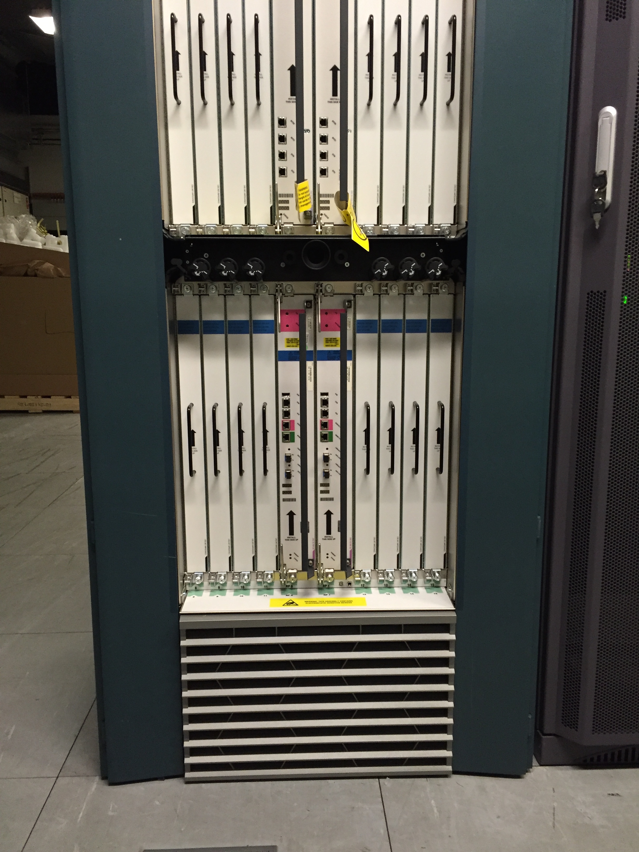
Line Card Chassis – front view
FCC – the Fabric Chassis is where all the Fabric Cards (S2) is placed, whereas the S13 Fabric Cards are placed to the Line Card Chassis. The most important thing to remember is that all the S13 cards from the LCC are connected to the S2 cards via the Array Cables. So, one chassis (in a 2+1 scenario) is used for the Fabric Card placement, and two additional Chassis will be used for the Line Card placement, improving the scalability as well as capacity of packet forwarding. Don’t forget, a FCC differs from a LCC physically, so both of them have different PID’s when purchasing.
Below is a picture of the front and rear view of a Fabric Card Chassis:
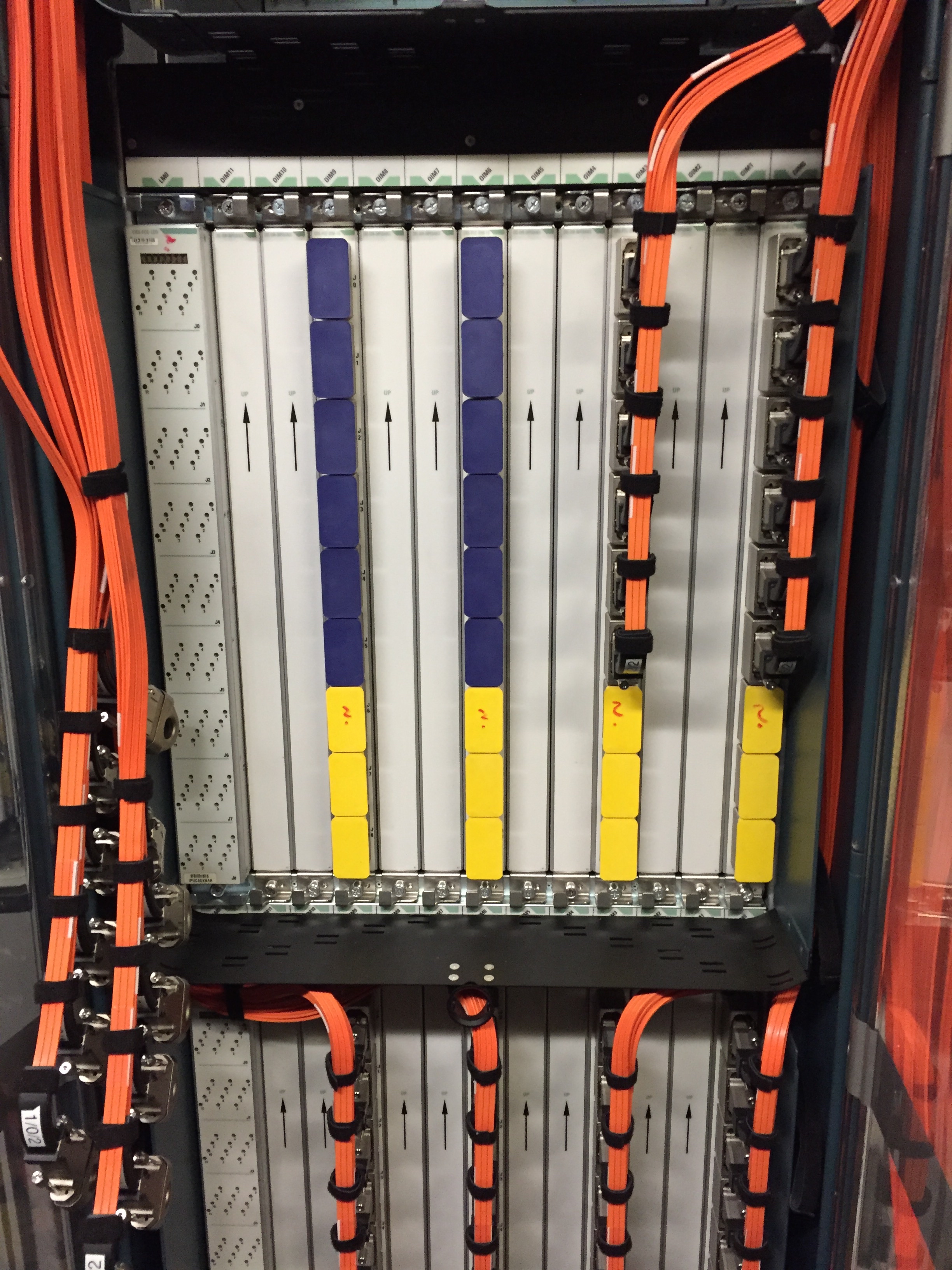
Fabric Card Chassis – rear view
S13 Fabric Cards – are being used on the LCC, eight (7 Fabric Cards are active and 1 is being used as a backup in case of a failure scenario) S13 fabric cards are needed on each LCC for the interconnection with the S2 fabric cards on the FCC via the Array cables. Each S13 card has 3 Fiber Optical Bundle Ports. Below is a picture of a S13 Fabric Card:
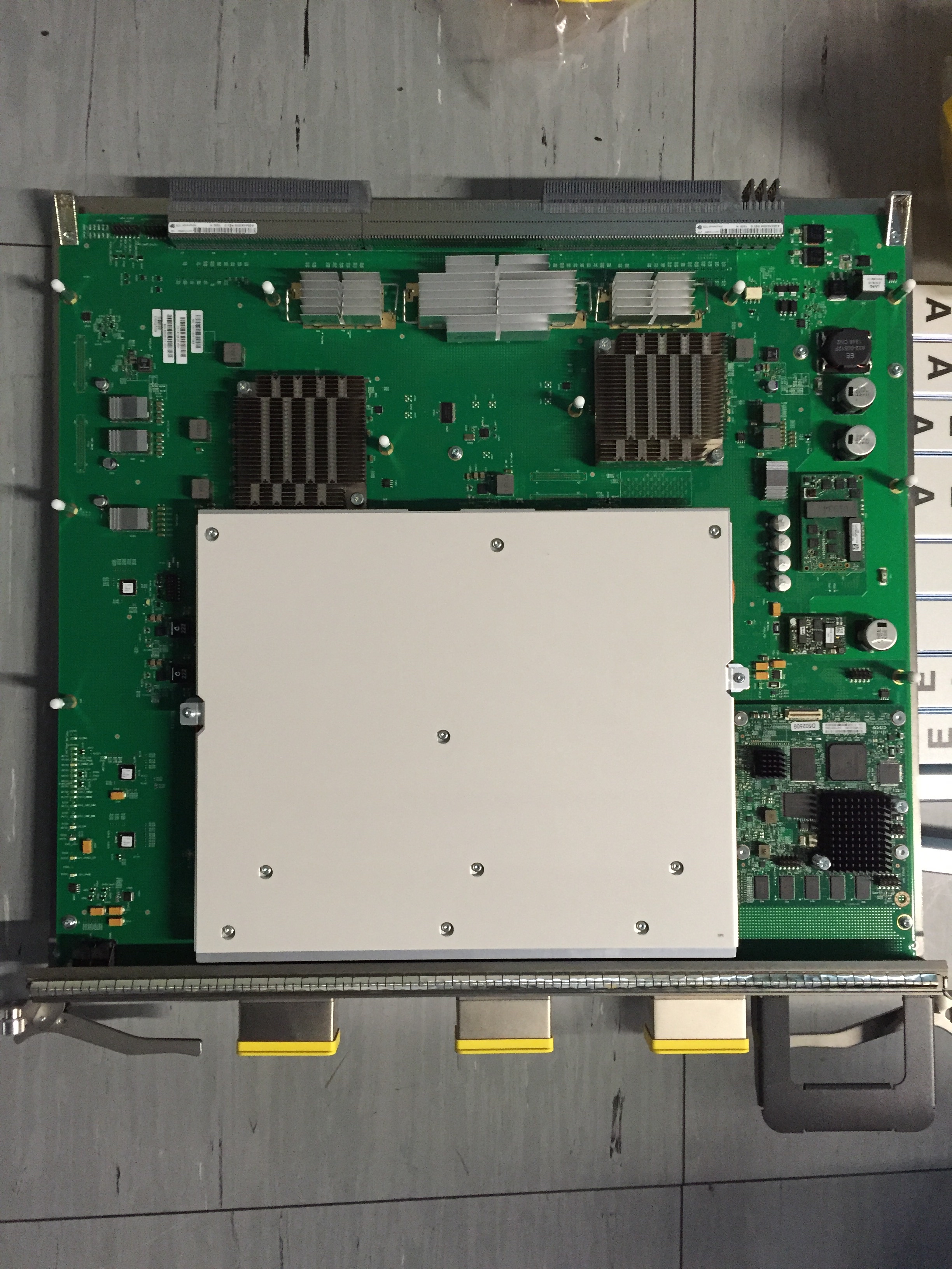
S13 Fabric Card
S2 Fabric Cards – are placed on the FCC, same as in the LCC here we need eight S2 fabric cards in a 2+1 scenario that connects to S13 cards of both LCC’s in the topology via the OIM modules on the rear of the FCC. Each S2 card has a 1to1 connection to an OIM module that is placed in the rear of FCC, and each OIM modules has 9 Fiber Optical Bundle Ports.
Optical Interface Modules – are basically passive cards interconnecting the Array cables on the FCC, the OIM’s are installed on the rear of the FCC chassis. They are directly connected to a S2 Fabric Card’s that are placed in the front of a FCC. There is no intelligence being used on the OIM’s.
Fabric Cables (Array Cables) – each bundle consists of 72 Optical Fibers, a bundle is considered a single physical port on an OIM module, which is connected to the S2 cards of the FCC. Below is a picture of an Array Cable:
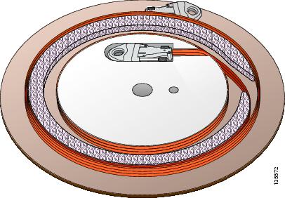
Array Cable
For more information on Fabric Cabling please check following link.
SCGE card – are installed on the FCC, 2 of these cards are needed for redundancy purposes, where one is active and the other one acts as a standby. One SCGE card is placed on the right most slot on the upper side of the shelf, whereas the second SCGE card is installed on the exact same slot on the lower part of the shelf. These cards are mainly used for control and management of the chassis; failure to start and boot-up correctly of SCGE cards causes the whole chassis to not power on.
Below is a picture that I made on one of the FCC’s I used to work on; SCGE card is the one on the first slot from the right:

SCGE Card
Having all of the information’s in mind from above let me add something regarding the installation and placement of the physical parts:
- On a Fabric Card Chassis always install physically the OIM modules first on the rear of the chassis, and then install the corresponding Fabric Card on the exact same slot from the front side.
- Install the OIM Led Module on the correct slot before installing the SCGE card.
- Start the Fabric cabling (I might have a new blog-post regarding the fabric cabling) between LCC and FCC, take care when moving and rolling the Array Cables, they are very sensitive, and follow the cabling scheme, since it is very important to have proper fabric cabling in place.
Above are some basic tasks that need to be followed; as soon as we have that in place what needs to be done is power on the first Line Card Chassis (LCC0) from the 2+1 Multi-chassis scenario, and do the following mandatory configuration on the Admin Configuration mode:
dsc serial TBA12345678 rack 0
dsc serial TBA87654321 rack 1
dsc serial TBA12348765 f0
!
controllers fabric plane 0
oim count 1
oim width 1
oim instance 0 location F0/SM0/FM
!
controllers fabric plane 1
oim count 1
oim width 1
oim instance 0 location F0/SM3/FM
!
controllers fabric plane 2
oim count 1
oim width 1
oim instance 0 location F0/SM6/FM
!
controllers fabric plane 3
oim count 1
oim width 1
oim instance 0 location F0/SM9/FM
!
controllers fabric plane 4
oim count 1
oim width 1
oim instance 0 location F0/SM12/FM
!
controllers fabric plane 5
oim count 1
oim width 1
oim instance 0 location F0/SM15/FM
!
controllers fabric plane 6
oim count 1
oim width 1
oim instance 0 location F0/SM18/FM
!
controllers fabric plane 7
oim count 1
oim width 1
oim instance 0 location F0/SM21/FM
!
The serial numbers configured above are the serial numbers of each chassis (LCC0, LCC1 and FCC). And the fabric plane configuration mostly is a standard one. With the above configuration on the LCC0 you should be ready to power on the FCC (considering that Fabric Cabling and RP to SCGE card cabling is in place) and the FCC should be able to recognize the LCC0.
After FCC and LCC0 recognize themselves as part of the Multi-chassis you can power on the second Line Card Chassis (LCC1).
Categories: General Networking

Leave a Reply