Dynamic Multipoint VPN is a technique and answer to the huge increase of Enterprise or Corporations remote sites or branches connecting to the HQ offices while in the same time maintain low costs (no need to purchase MPLS VPN services or extra circuits from Service Providers), way easier administration of site’s and faster deployment of new sites. To explain how DMVPN works we have to take advantage of following protocols:
1) Multipoint GRE – mGRE
2) Next hop resolution protocol – NHRP
3) Some of routing protocols (OSPF, EIGRP, RIP, etc)
4) IPsec – Optionally
Multipoint GRE works the same as a single GRE tunnel between two end-points, the only difference is that with mGRE we don’t have to specify the tunnel destination.
NHRP is a protocol or the “Engine” when it comes to DMVPN deployment, so NHRP takes care of the mapping between the Hub and Spokes site dynamically.
Let’s see our basic topology in the beginning:
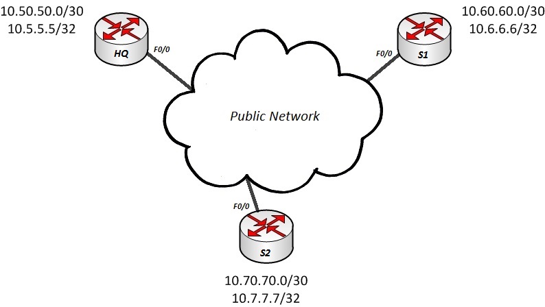
I have preconfigured EIGRP on all router interfaces (Hub-HQ, S1 and S2) except on the interfaces connecting to Public Network, but of course they still can’t advertise each other their networks because we still didnt create the mGRE tunnels.
The following are the Public IP addresses of the routers:
– HQ F0/0 (15.1.1.1)
– S1 F0/0 (15.2.2.1)
– S2 F0/0 (15.3.3.1)
Now let’s hop in and configure the mGRE on the Hub or the HQ office which is going to act as a Next Hop Server (NHS) which also holds the NHRP database for all Spoke sites which is the key point in DMVPN functionality:
interface Tunnel0
description mGRE
ip address 192.168.0.1 255.255.255.0
no ip redirects
ip nhrp map multicast dynamic
ip nhrp network-id 1
tunnel source 15.1.1.1
tunnel mode gre multipoint
“ip nhrp map multicast dynamic” – this commands ensures that multicast traffic is allowed between the Hub and Spokes which is crucial because Routing Protocols such as OSPF, EIGRP, RIP use Multicast for their control plane functionality.
“ip nhrp network-id 1” – this command defines the network identification, so all spokes that want to participate to this DMVPN network should have the same id.
“tunnel source 15.1.1.1” – this command ensures that our Public IP is used as the source as long as it arrives to the other spokes when traffic is passing through the tunnel.
“tunnel mode gre multipoint” – this command defines the tunnel as gre multipoint, so no need for static destination configuration because NHRP will take care of all the dynamic destinations coming in and out.
Next thing would be to configure the Spokes (S1, S2), let’s do it:
On S1:
interface Tunnel0
description R2 mGRE
ip address 192.168.0.2 255.255.255.0
no ip redirects
ip nhrp map multicast dynamic
ip nhrp map 192.168.0.1 15.1.1.1
ip nhrp map multicast 15.1.1.1
ip nhrp network-id 1
ip nhrp nhs 192.168.0.1
tunnel source FastEthernet0/0
tunnel mode gre multipoint
On S2:
interface Tunnel0
description R3 mGRE
ip address 192.168.0.3 255.255.255.0
no ip redirects
ip nhrp map multicast dynamic
ip nhrp map 192.168.0.1 15.1.1.1
ip nhrp map multicast 15.1.1.1
ip nhrp network-id 1
ip nhrp nhs 192.168.0.1
tunnel source FastEthernet0/0
tunnel mode gre multipoint
“ip nhrp map 192.168.0.1 15.1.1.1” – This command maps the tunnel ip address of HQ router with the Public IP address of the same.
“ip nhrp map multicast 15.1.1.1” – This command ensures that multicast traffic will be enabled to the HQ router which is our Hub site.
“ip nhrp nhs 192.168.0.1” – This command configures the IP address of the Next Hop Server (HQ Router) which will be used always for every destination to other Spokes.
Let’s see now the full picture of our configured DMVPN solution:

So now we should have visibility to all networks Hub-Spoke and Spoke-Spoke but remember to disable split-horizon on the HQ because the Spokes will not have reachability to each other if you use EIGRP without disabling split-horizon. Let’s check the Routing Table on HQ:
HQ#show ip route | s 10.60.60.0
D 10.60.60.0/30 [90/297270016] via 192.168.0.2, 01:46:55, Tunnel0
HQ#show ip route | s 10.6.6.6
D 10.6.6.6/32 [90/297398016] via 192.168.0.2, 01:47:04, Tunnel0
HQ#show ip route | s 10.70.70.0
D 10.70.70.0/30 [90/297270016] via 192.168.0.3, 01:48:29, Tunnel0
HQ#show ip route | s 10.7.7.7
D 10.7.7.7/32 [90/297398016] via 192.168.0.3, 01:48:34, Tunnel0
From HQ we have visibility and connectivity to all the networks behind the Spokes (S1 and S2). Let’s check the same from one of our Spoke (S1):
S2#show ip route | s 10.50.50.0
D 10.50.50.0/30 [90/297270016] via 192.168.0.1, 01:50:17, Tunnel0
S2#show ip route | s 10.70.70.0
D 10.70.70.0/30 [90/310070016] via 192.168.0.1, 01:50:23, Tunnel0
S2#show ip route | s 10.7.7.7
D 10.7.7.7/32 [90/310198016] via 192.168.0.1, 01:50:28, Tunnel0
From S1 Routing Table we can see all the networks behind HQ and S2 aswell, let’s try to trace the destinatin 10.7.7.7 in order to verify that the traffic is going through the hub to reach the destination which is behind S2:
S2#traceroute 10.7.7.7
Tracing the route to 10.7.7.7
1 192.168.0.1 100 msec 208 msec 168 msec
2 192.168.0.3 80 msec 56 msec 104 msec
3 10.70.70.2 84 msec * 124 msec
Sure enough, hop 2 tells us clearly that this is the tunnel IP address of HQ.
This DMVPN configuration example used only GRE encapsulation without any IPsec encryption, to add encryption we need to configure crypto maps so that the traffic cannot be intercepted somewhere in the Public Network.
Categories: General Networking

Leave a Reply