This time I will try to explain how to achieve passing the Transit traffic without affecting our internal domain of having all the externall routes, at least from the Control Plane point of view, because the Data Plane traffic however will pass through our internal devices.
So, let’s say our Autonomous System number is 10, our directly connected BGP neighbor AS-es are 20 and 30.

Normally we would need to have a full-mesh BGP neighborship in our AS 10 or having redistribution in place to pass the transit traffic from our Ingress point (our Edge where the traffic comes from, can be R3 or R4) to the Egress point (you guess what this one does..), or MPLS/VPN, but sometimes we don’t want all the Internet routes be propagated inside our AS, especially nowadays when we are reaching around 500.000 IPv4 global routes. This is a huge number and imagine one of our IGP-s handling this amount of routes, simply OVERKILL.
Now let’s jump to one of the solutions to this, how could we achieve this without redistributing BGP routes to IGP (OSPF, EIGRP, or RIP!), and without implementing Full-Mesh BGP neighborship in our AS (R1, R2, R3, R4).
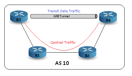
As a solution we can use Tunnels between our Edge devices (R3 and R4) so that Data Traffic will follow the path through the Tunnel while the Control Traffic will follow the normal path through R3 -> R1 <–> R2 <- R4. Let’s see the picture below for a visual understanding.
Below some information about the IP configuration on our devices:
– R3, loopback0 IP address (3.3.3.3).
– R3, Fe0/0 IP address (10.1.13.2), connected to R1 Fe0/0.
– R1, loopback0 IP address (1.1.1.1).
– R1, Fe0/0 IP address (10.1.13.1), connected to R3 Fe0/0.
– R1, Fe1/0 IP address (10.1.12.1), connected to R2 Fe0/0.
– R2, loopback0 IP address (2.2.2.2).
– R2, Fe0/0 IP address (10.1.12.2), connected to R1 Fe1/0.
– R2, Fe1/0 IP address (10.1.24.1), connected to R4 Fe0/0.
– R4, loopback0 IP address (4.4.4.4).
– R4, Fe0/0 IP address (10.1.24.2), connected to R2 Fe1/0.
We are running OSPF in area 0 on AS 10, our internal routers (R1, R2) don’t have visibility on external routes. We are running iBGP between R3 and R4 and BGP control packets follow the path through R1, R2 normally. So the question is what if we receive a data packet from AS 30, and this packet should be forwarded through our AS to the AS 20.
Let’s try this one, we will generate a icmp packet on R8 as source (8.8.8.8), and destination will be R5 (5.5.5.5).

And below output from R2 explains why the packet didn’t pass through:

When the packet sourced as 8.8.8.8 arrived at R2, R2 made a lookup on it’s FIB and found that the destination 5.5.5.5 is not in his table, so he responds back to R8 that the destination you are trying to reach through me is not in my RIB/FIB, so the packet is dropped.
Now let’s move on and configure the Tunnel’s on R3 and R4:
On R3:
interface Tunnel0
ip address 192.168.1.1 255.255.255.252
tunnel source 10.1.13.2
tunnel destination 10.1.24.2
On R4:
interface Tunnel0
ip address 192.168.1.2 255.255.255.252
tunnel source 10.1.24.2
tunnel destination 10.1.13.2
Tunnel source and destination’s are normally physical IP addresses of both routers connected to R1 respctivelly R2 on both sides. Now if we try the same Ping from R8 to R5 again we will face the same issue, a dropped packet as soon as it arrives on R2. The next and last thing we have to do is to tell R3 and R4 that every BGP update/advertisement between them should use as next-hop the Tunnel interfaces. In this way the BGP Control Plane packets will go through the normal path, but the Data Plane packets (Transit traffic) will go through the Tunnel interface, this is the way to split the paths of Control and Data plane traffic in BGP.
Let’s configure the Route maps to point as next hop to Tunnel interfaces and apply them on BGP:
On R3:
route-map r4_next-hop permit 10
set ip next-hop 192.168.1.2
!
router bgp 10
neighbor 4.4.4.4 route-map r4_next-hop in
!
On R4:
route-map r3_next-hop permit 10
set ip next-hop 192.168.1.1
!
router bgp 10
neighbor 3.3.3.3 route-map r3_next-hop in
!
At this point we should have connectivity between AS 30 and AS 20 through our AS 10 without full visibility of the external routes on R1 and R2 which was our primary intention.
Let’s debug some packets on R2 or R1 which are not running BGP at all, we will again generate an icmp packet as source 8.8.8.8 and destination 5.5.5.5, and see what happens:

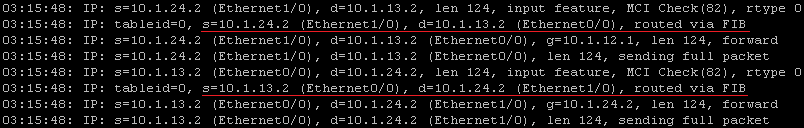
With the output above we confirm that by using Tunnels between our Edge iBGP routers for Transit traffic is one of the solutions to not run BGP inside our domain on all routers, because let’s imagine we have more than 50 devices, so having 50 neighbors on every device is not neccessary, especially when you have an Enterprise that cannot handle the overhead of BGP and IGP together or if we dont want to have all the routes visible inside our AS.
Categories: General Networking

Leave a Reply