MPLS Traffic engineering is a set of tools that can improve performance in MPLS based networks.
Let’s have a look at some terminologies when deploying MPLS Traffic Engineering:
- Head-End (Ingress PE)
- Tail-End (Egress PE)
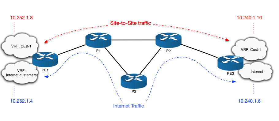
Looking at the diagram below, we can safely assume that PE1, PE2, and PE3 might play the role of Ingress and Egress PE at the same time (depending whether the traffic is coming from a directly connected customer and forward towards the Core network to reach other PE’s, or the incoming traffic is coming from the Core network and forwarded towards the directly connected customer on the PE itself).

There are some methods of doing Traffic Engineering, however until recently RSVP-TE was the only choice of doing it. Though, still possible, however on the other hand it’s extremely difficult to maintain and operate a network with RSVP.
As this topic is about Segment Routing Traffic engineering, RSVP is out of scope.
Segment Routing (RFC 8402) has been defined as a new standard to forward packets based on different data plane methodologies such as: MPLS, or IPv6 (SRv6). There are tremendous benefits of migrating your MPLS (LDP/RSVP) network to Segment Routing, such as:
- 100% Traffic Protection in any topology (Ti-LFA)
- ECMP Traffic load-balancing (default nature of SR)
- Stateless Traffic Engineering (the core router doesn’t need to keep state of the tunnels)
- Data/Control plane separation (with SDN controller)
- and much more..
Coming back to the topic, while SR-TE can help designing different patterns of routing the traffic in a network, it is important also to be able to separate the customer specific traffic between e.g; Site-1 and Site-2, and the Internet traffic.
This scenario is based on real production deployments, considering Internet traffic requires a lot of bandwidth, whereas site-to-site traffic doesn’t need much of bandwidth, however this type of traffic is delay sensitive, so based on capacity management the Network Operator decides to use the end-to-end 100G path (PE1 <-> P1 <-> P3 <-> P2 <-> PE3) for Internet traffic. And for delay sensitive traffic the Operator decided to use the shortest-path (PE1 <-> P1 <-> P2 <-> PE3).
Considering the diagram below, we already assigned Segment Routing SIDs for specific Loopback interface on each of the device. PE1 and PE3 are the only routers with two Loopback interfaces (Lo0 for site-to-site traffic and Lo100 for Internet traffic).

PE1 and PE3 are IOS-XE based devices (csr1000v), whereas P1, P2, and P3 are IOS-XR devices.
Segment Routing with MPLS data plane, and IS-IS as IGP are deployed here. Let’s have a look at the configuration of PE1:
## Configuration on PE1, the same applied on PE3 with specific IP addressing schema ##
 !
 vrf definition Internet-traffic
  rd 10:10
  route-target export 10:10
  route-target import 10:10
  !
  address-family ipv4
  exit-address-family
  !
 !
 vrf definition Cust-1
  rd 20:20
  route-target export 20:20
  route-target import 20:20
  !
  address-family ipv4
  exit-address-family
  !
 !
 mpls traffic-eng tunnels
 !
 !
 segment-routing mpls
  !
  connected-prefix-sid-map
   address-family ipv4
    172.17.17.11/32 absolute 16011 range 1
    100.100.100.1/32 absolute 17011 range 1
   exit-address-family
  !
  !
 interface Loopback0
  ip address 172.17.17.11 255.255.255.255
 !
 interface Loopback100
  ip address 100.100.100.1 255.255.255.255
 !
 !
 router isis CORE
  ...
  segment-routing mpls
  fast-reroute per-prefix level-2 all
  fast-reroute ti-lfa level-2
  mpls traffic-eng router-id Loopback0
  mpls traffic-eng level-2
 !
 router bgp 65000
  ...
  !
  address-family ipv4
  exit-address-family
  !
  address-family vpnv4
   neighbor 172.17.17.13 activate
   neighbor 172.17.17.13 send-community both
   neighbor 172.17.17.13 next-hop-self
  exit-address-family
  !
  address-family ipv4 vrf Internet-traffic
   redistribute connected
   ...
  exit-address-family
  !
  !
  address-family ipv4 vrf Cust-1
   redistribute connected
   ...
  exit-address-family
  !
 !
The same template configuration is applied on PE3.
Now, for Internet traffic, let’s configure a tunnel on PE1 pointing to PE3 by using Interface Loopback100 as source, and IP address of Lo100 of PE3 as destination. We can create a static route pointing to remote loopback100 interface as next-hop, or we can use ‘autoroute destination’ under tunnel configuration as below:
 !
 interface Tunnel100
  ip unnumbered Loopback100
  tunnel mode mpls traffic-eng
  tunnel destination 100.100.100.2
  tunnel mpls traffic-eng autoroute destination
  tunnel mpls traffic-eng path-option 4 explicit name srte_path segment-routing
 !
 !
 ip explicit-path name srte_path enable
  index 10 next-label 16001
  index 20 next-label 16003
  index 30 next-label 16002
  index 40 next-label 17013
 !
The Label values (Prefix Segment IDs) in explicit-path list above are based on the previous SID assignment and the local Adjacency-SID of specific router on the path towards PE3.
And last, since we created two Loopbacks on PE’s, we need to make sure that all Internet traffic is pointing to correct Loopback (in our case Loopback100), and this is done under the address-family of specific VRF:
!
 vrf definition Internet-traffic
  …
  !
  address-family ipv4
   bgp next-hop Loopback100
  exit-address-family
  !
 !
Based on the diagram above, let’s test the solution by executing a traceroute from the VRF Cust-1 first:
 customer1#traceroute vrf Cust-1 10.240.1.10
 Type escape sequence to abort.
 Tracing the route to 10.240.1.10
 VRF info: (vrf in name/id, vrf out name/id)
   1 10.252.1.9 1 msec 1 msec 1 msec
   2 10.0.0.18 [MPLS: Labels 16013/25 Exp 0] 11 msec 10 msec 10 msec
   3 10.0.0.6 [MPLS: Labels 16013/25 Exp 0] 10 msec 11 msec 11 msec
   4 10.240.1.9 11 msec 10 msec 11 msec
   5 10.240.1.10 13 msec *  12 msec
 customer1#
And now, let’s test the SR-TE solution of routing the Internet-traffic via an explicit path:
 customer1#traceroute vrf Internet-traffic 10.240.1.6
 Type escape sequence to abort.
 Tracing the route to 10.240.1.6
 VRF info: (vrf in name/id, vrf out name/id)
   1 10.252.1.5 1 msec 1 msec 1 msec
   2 10.0.0.18 [MPLS: Labels 16003/16002/17013/24 Exp 0] 26 msec 13 msec 14 msec
   3 10.0.0.10 [MPLS: Labels 16002/17013/24 Exp 0] 21 msec 13 msec 12 msec
   4 10.0.0.13 [MPLS: Labels 17013/24 Exp 0] 12 msec 13 msec 14 msec
   5 10.240.1.5 16 msec 14 msec 14 msec
   6 10.240.1.6 14 msec *  17 msec
 customer1#
Conclusion: Segment Routing Traffic Engineering is powerful, as you don’t need any additional Signalling protocol (RSVP) or LDP to implement any sort of explicit or dynamic routing for specific customer, or specific service. SR-TE combined with SDN Controllers such the Cisco XTC or any other open-source controller provides the capability to split the control plane from the forwarding devices, which gives the flexibility to the underlay routers to focus only by forwarding the traffic, while the route calculations are provided by the controller.
Categories: General Networking

Leave a Reply